3.2: Motion and position sensors
Contents:
- Introduction
- Coordinate systems
- Device orientation
- Device rotation
- Motion sensors
- Position sensors
- Related practical
- Learn more
You can use motion and position sensors to monitor a device's movement or its position in space.
Use the classes and methods from the Android sensor framework to gain access to the motion and position sensors and to handle changes to sensor data.
All the motion sensors return multi-dimensional arrays of sensor values for each SensorEvent. For example, during a single sensor event the accelerometer returns acceleration force data for the three coordinate axes ( x , y , z ) relative to the device.
In this chapter you learn more about the motion and position sensors and how to manage the data they produce. In a later part of this chapter, you learn about the most common motion and position sensors.
Coordinate systems
The motion and position sensors in Android typically use two different coordinate systems: a device coordinate system relative to the device, and a coordinate system relative to the surface of the Earth. Both systems use a standard 3-axis system ( x , y , z ). In addition, some sensors and methods in the Android sensor framework provide their data as angles around the three axes.
Device coordinates
Most Android sensors, including the accelerometer and gyroscope, use a standard 3-axis coordinate system defined relative to the device's screen when the device is held in its default orientation (portrait orientation, for a phone). In the standard 3-axis coordinate system, the x -axis is horizontal and points to the right. The y -axis is vertical and points up, and the z -axis points toward the outside of the screen face. In this system, coordinates behind the screen have negative z values.
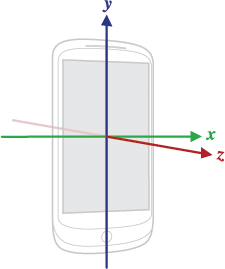
The most important point to understand about this coordinate system is that, unlike activity rotation, the axes are not swapped when the device's screen orientation changes—that is, the sensor's coordinate system never changes as the device rotates. This behavior is the same as the behavior of the OpenGL coordinate system.
If your app uses sensor data to position views or other elements on the screen, you need to transform the incoming sensor data to match the rotation of the device. See Device rotation for more information.
Your app must not assume that a device's natural (default) orientation is portrait. The natural orientation for many tablet devices is landscape. And the sensor coordinate system is always based on the natural orientation of a device.
Earth's coordinates
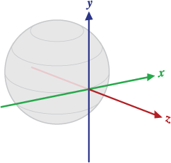
Some sensors and methods use a coordinate system that represents device motion or position relative to the Earth. In this coordinate system:
- y points to magnetic north along the surface of the Earth.
- x is 90 degrees from y , pointing approximately east.
- z extends up into space. Negative z extends down into the ground.
Determining device orientation
Device orientation is the position of the device in space relative to the Earth's coordinate system (specifically, to the magnetic north pole). You can use orientation for compass apps, or to determine the degree of tilt for the device for games.
Although early versions of Android included an explicit sensor type for orientation (Sensor.TYPE_ORIENTATION), this sensor type was deprecated in API 8 and may be entirely unavailable in current devices.
The recommended way to determine device orientation uses the accelerometer and geomagnetic field sensor and several methods in the SensorManager class. The following code shows you how to compute a device's orientation:
private SensorManager mSensorManager;
...
// Rotation matrix based on current readings from accelerometer and magnetometer.
final float[] rotationMatrix = new float[9];
mSensorManager.getRotationMatrix(rotationMatrix, null,
  accelerometerReading, magnetometerReading);

// Express the updated rotation matrix as three orientation angles.
final float[] orientationAngles = new float[3];
mSensorManager.getOrientation(rotationMatrix, orientationAngles);
The getRotationMatrix() method generates a rotation matrix from the accelerometer and geomagnetic field sensor. A rotation matrix is a linear algebra concept that translates the sensor data from one coordinate system to another—in this case, from the device's coordinate system to the Earth's coordinate system.
The getOrientation() method uses the rotation matrix to compute the angles of the device's orientation. All of these angles are in radians, with values from -π to π. There are three components to orientation:
Azimuth : The angle between the device's current compass direction and magnetic north. If the top edge of the device faces magnetic north, the azimuth is 0.
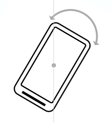
Pitch : The angle between a plane parallel to the device's screen and a plane parallel to the ground.
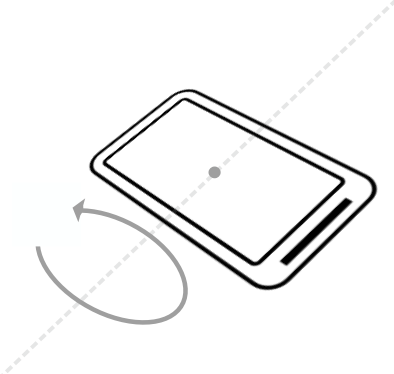
Roll : The angle between a plane perpendicular to the device's screen and a plane perpendicular to the ground.
Understanding device rotation
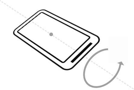
If your app draws views on the screen in positions based on sensor data, you need to transform the sensor's coordinate system (which does not rotate) with the screen or activity's coordinate system (which does rotate).
To handle device and activity rotation in sensor-based drawing, query the current device orientation with the getRotation() method. Then remap the rotation matrix from the sensor data onto the desired axes with the remapCoordinateSystem() method.
The getRotation() method returns one of four integer constants:
ROTATION_0: The default orientation of the device (portrait for phones).ROTATION_90: The "sideways" orientation of the device (landscape for phones). Different devices may report 90 degrees either clockwise or counterclockwise from 0.ROTATION_180: Upside-down orientation, if the device allows it.ROTATION_270: Sideways orientation, in the opposite direction fromROTATION_90.
Many devices do not have ROTATION_180 at all. Many devices return ROTATION_90 or ROTATION_270, regardless of whether the device was rotated clockwise or counterclockwise. It is best to handle all possible rotations rather than to make assumptions about any particular device.
The following sample code shows how to use getRotation() and remapCoordinateSystem() to get the rotation for the device.
// Compute the rotation matrix: merges and translates the data
// from the accelerometer and magnetometer, in the device coordinate
// system, into a matrix in Earth's coordinate system.
//
// The second argument to getRotationMatrix() is an
// inclination matrix, which isn't used in this example (and
// is thus null).
float[] rotationMatrix = new float[9];
boolean rotationOK = SensorManager.getRotationMatrix(rotationMatrix,
       null, mAccelerometerData, mMagnetometerData);

// Remap the matrix based on current device/activity rotation.
float[] rotationMatrixAdjusted = new float[9];
switch (mDisplay.getRotation()) {
   case Surface.ROTATION_0:
       rotationMatrixAdjusted = rotationMatrix.clone();
       break;
   case Surface.ROTATION_90:
       SensorManager.remapCoordinateSystem(rotationMatrix,
               SensorManager.AXIS_Y, SensorManager.AXIS_MINUS_X,
               rotationMatrixAdjusted);
       break;
   case Surface.ROTATION_180:
       SensorManager.remapCoordinateSystem(rotationMatrix,
               SensorManager.AXIS_MINUS_X, SensorManager.AXIS_MINUS_Y,
               rotationMatrixAdjusted);
       break;
   case Surface.ROTATION_270:
       SensorManager.remapCoordinateSystem(rotationMatrix,
               SensorManager.AXIS_MINUS_Y, SensorManager.AXIS_X,
               rotationMatrixAdjusted);
       break;
}
Motion sensors
The Android platform provides several sensors that let you monitor device motion such as tilt, shake, rotation, or swing. The movement is usually a reflection of direct user input, for example a user steering a car in a game, or a user controlling a ball in a game. Movement can also be a reflection of the device's physical environment, for example the device moving with you while you drive your car.
- When movement is a reflection of direct user input, you are monitoring motion relative to the device's frame of reference, or your app's frame of reference.
- When movement is a reflection of the device's physical environment, you are monitoring motion relative to the Earth.
Motion sensors by themselves are not typically used to monitor device position, but they can be used with other sensors, such as the geomagnetic field sensor, to determine a device's position relative to the Earth's frame of reference.
This section describes many of the most common Android motion sensors. It is not a comprehensive list of all the motion sensors available in the Android sensor framework. See Motion Sensors and the Sensor class for more information.
Accelerometer
The accelerometer (TYPE_ACCELEROMETER) measures the acceleration applied to the device along the three device axes ( x , y , z ), including the force of gravity. The inclusion of the force of gravity means that when the device lies flat on a table, the acceleration value along the z -axis is +9.81. This corresponds to the acceleration of the device (0 m/s^2) minus the force of gravity (-9.81 m/s^2). A device in freefall has a z value of 0, because the force of gravity is not in effect.
If you need only the acceleration forces without gravity, use the TYPE_LINEAR_ACCELERATION virtual sensor. If you need to determine the force of gravity without acceleration forces, use the TYPE_GRAVITY virtual sensor.
Nearly every Android-powered handset and tablet has an accelerometer in hardware. The accelerometer uses many times less power than other motion sensors. However, the raw accelerometer data is quite noisy and you may need to implement filters to eliminate gravitational forces and reduce noise. See this stack overflow question for more information on filtering accelerometer data.
The event data generated by the accelerometer is as shown in the following table:
| Event data | Description | Units |
SensorEvent.values[0]
|
Acceleration force along the x -axis (including gravity). | m/s2 |
SensorEvent.values[1]
|
Acceleration force along the y -axis (including gravity). | m/s2 |
SensorEvent.values[2]
|
Acceleration force along the z -axis (including gravity). | m/s2 |
The following code shows you how to get an instance of the default linear acceleration sensor:
private SensorManager mSensorManager;
private Sensor mSensor;
...
mSensorManager = (SensorManager) getSystemService(Context.SENSOR_SERVICE);
mSensor = mSensorManager.getDefaultSensor(Sensor.TYPE_LINEAR_ACCELERATION);
Gravity sensor
The gravity sensor (TYPE_GRAVITY) measures the force of gravity along the three device-coordinate axes ( x , y , z ). Although gravity can be a hardware sensor, it is typically a virtual sensor based on data from the accelerometer. When a device is at rest, the output of the gravity sensor should be identical to that of the accelerometer.
The event data generated by the gravity sensor is as shown in the following table:
| Event data | Description | Units |
| SensorEvent.values[0] | Force of gravity along the x -axis. | m/s2 |
| SensorEvent.values[1] | Force of gravity along the y -axis. | m/s2 |
| SensorEvent.values[2] | Force of gravity along the z -axis. | m/s2 |
Gyroscope
The gyroscope sensor (TYPE_GYROSCOPE) measures the rate of rotation around the three device axes ( x , y , z ). All values are in radians/second. Although you can use the gyroscope to determine the orientation of the device, it is generally better practice to use the accelerometer with other sensors such as the magnetometer.
Many current devices have a gyroscope sensor, although the gyroscope may be unavailable in older or lower-end devices.
The event data generated by the gyroscope sensor is as shown in the following table:
| Event data | Description | Units |
SensorEvent.values[0]
|
Rate of rotation around the x -axis. | rad/s |
SensorEvent.values[1]
|
Rate of rotation around the y -axis. | rad/s |
SensorEvent.values[2]
|
Rate of rotation around the z -axis. | rad/s |
Linear accelerator
The linear accelerator (TYPE_LINEAR_ACCELERATION) measures acceleration forces applied to the device along the three device axes ( x , y , z ), minus the force of gravity. Linear acceleration is usually a software sensor that gets its data from the accelerometer.
The event data generated by the linear acceleration sensor is as shown in the following table:
| Event data | Description | Units |
SensorEvent.values[0]
|
Acceleration on the x -axis. | m/s2 |
SensorEvent.values[1]
|
Acceleration on the y -axis. | m/s2 |
SensorEvent.values[2]
|
Acceleration on the z -axis. | m/s2 |
Rotation-vector sensor
The rotation-vector sensor (TYPE_ROTATION_VECTOR) provides the orientation of the device with respect to Earth's coordinate system as a unit quaternion. Specifically, the rotation vector represents the orientation of the device as a combination of an angle and an axis, in which the device has rotated through an angle θ around an axis < x , y , z >. The first four elements of the rotation vector are equal to the components of a unit quaternion
The rotation-vector sensor is a software sensor that integrates data from the accelerometer, magnetometer, and gyroscope (if available). If you are comfortable with the math, the rotation vector is a more efficient and a more accurate way to determine device orientation than other methods.
The event data generated by the rotation-vector sensor is as shown in the following table:
| Event data | Description | Units |
SensorEvent.values[0]
|
x *sin(θ/2) | none |
SensorEvent.values[1]
|
y *sin(θ/2) | none |
SensorEvent.values[2]
|
z *sin(θ/2) | none |
SensorEvent.values[3]
|
cos(θ/2) (API 18 and higher only) | none |
SensorEvent.values[4]
|
Estimated direction (heading) accuracy, -1 if unavailable (API 18 and higher only) | radians |
Step counter and step detector
The step-counter sensor (TYPE_STEP_COUNTER) measures the number of steps taken by the user since the last reboot, while the sensor was registered and active. The step counter is a hardware sensor that has more latency (up to 10 seconds) but more accuracy than the step-detector sensor (see below). To preserve the battery on devices running your app, you should use the JobScheduler class to retrieve the current value from the step-counter sensor at a specific interval. Although different types of apps require different sensor-reading intervals, you should make this interval as long as possible unless your app requires real-time data from the sensor.
The event value for the step counter (value[0]) is a floating-point number with the fractional part set to zero. The value is reset to zero only on a system reboot. The timestamp of the event is set to the time when the last step for that event was taken.
The step-detector sensor (TYPE_STEP_DETECTOR) is a hardware sensor that triggers an event each time the user takes a step. Compared to the step counter, the step detector usually has a lower latency, less than 2 seconds.
The event value (value[0]) is always 1.0. The timestamp of the event corresponds to when the foot hits the ground.
See the BatchStepSample on GitHub for code that shows how to use the step-counter sensor and step-detector sensor.
Position sensors
Position sensors are useful for determining a device's physical position in the Earth's frame of reference. For example, you can use the geomagnetic field sensor in combination with the accelerometer to determine a device's position relative to the magnetic north pole, as in a compass app. Position sensors are not typically used to monitor device movement or motion.
Geomagnetic field sensor (magnetometer)
The geomagnetic field sensor (TYPE_MAGNETIC_FIELD), also known as the magnetometer, measures the strength of magnetic fields around the device on each of three axes ( x , y , z ), including the Earth's magnetic field. Units are in microtesla (uT). Most Android devices include a hardware-based geomagnetic field sensor.
You can use this sensor to find the device's position in respect to the external world, for example, to create a compass app. However, magnetic fields can also be generated by other devices in the vicinity, by external factors such as your location on Earth (the magnetic field is weaker toward the equator), or even from the current strength of solar winds. For a more accurate device orientation use the SensorManager class's getRotationMatrix() and getOrientation() methods, or the rotation-vector sensor.
The event data generated by the geomagnetic field sensor is as shown in the following table:
| Event data | Description | Units |
SensorEvent.values[0]
|
Magnetic field strength along the x -axis. | uT |
SensorEvent.values[1]
|
Magnetic field strength along the y -axis. | uT |
SensorEvent.values[2]
|
Magnetic field strength along the z -axis. | uT |
Orientation sensor
The orientation sensor (TYPE_ORIENTATION) measures degrees of rotation that a device makes around all three physical axes ( x , y , z ). Orientation was a software-only sensor that combined data from several other sensors to determine the position of the device in space. However, because of problems with the accuracy of the algorithm, this sensor type was deprecated in API 8 and may be entirely unavailable in current devices. For a more accurate device orientation use the SensorManager class's getRotationMatrix() and getOrientation() methods, or the rotation-vector sensor.
Related practical
The related practical documentation is in Working with Sensor-Based Orientation.
Learn more
Android developer documentation:
Android API reference documentation:
Other documentation:
- Accelerometer Basics
- Sensor fusion and motion prediction (written for VR, but many of the basic concepts apply to basic apps as well)
- Android phone orientation overview
- One Screen Turn Deserves Another